
Having taught our Arduino to pulse a little red LED slowly on and off, and having built the circuit to go with it, we wanted to do something a bit more complex. We considered adding a buzzer, or a button to modify the light’s behaviour – but the simplest next step seemed to be to add a second light, and then get it to behave differently from the first one.
The first decision we had to make was where to start: clearly we had to change the software and the hardware, but which should we do first? I left the choice up to William – he said we should modify the wiring first. Although I feel more secure in the abstract world of code than physical electronic components, this felt right somehow.
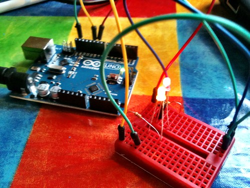
So we decided to copy what we’d done with the first LED, only using a new pin on the Arduino board. In our first project we connected a red LED to pin 9, so we chose pin 10 for our yellow LED. There was going to be a bit of a problem completing the circuit, though: we know all electrical circuits have to be complete and circular, and yet the Arduino only has one GND (earth) pin. I described it to William as if we had a battery with two + terminals, but only one – terminal.
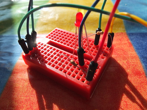
Using some vague idea of electronics I must have gained by osmosis (perhaps when I was breathing in all those solder flux fumes as a kid), I created what I confidently called a ‘ground rail’ on the breadboard. This is a common earth line that will complete both our light bulb circuits by connecting them back to the single GND pin on the Arduino.
At this point I had no idea if I was talking complete and utter homeopathy, but I ploughed on regardless.

So we rejigged our previous circuit with the red LED, taking a patch lead from the GND pin to a spare row on the breadboard, and then used another patch lead to connect it back to the LED. This spare row became our ground rail.
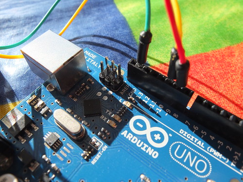
So, for our second LED, we took a jumper from pin 10, connected it to a new 330 ohm resistor, and connected that to one side of a yellow LED. The other side of the yellow LED we connected to our ground rail, to complete the circuit for the yellow light.
William was keen that the two LEDs should be next to each other, so we made the new circuit a physical mirror image on the breadboard of the first circuit.
So that’s the hardware – in theory. Just to check that I’d not gone totally off the (earth) rails, we connected this up to the power with the Arduino running the old code for one LED to see if it still worked. It did. No smoke, explosions – the red LED pulsed and the yellow LED did nothing, as you’d expect; we hadn’t told the Arduino that the yellow LED even existed, let alone what to do with it.
So the code… we did this in two or three steps. First we took the ‘Fade’ sample code and tweaked it so that it would control both LEDs in the same way:
/*
 Fade

 This example shows how to fade an LED on pin 9
 and another LED on pin 10 simultaneously
 using the analogWrite() function.

 */
int brightness = 0;    // how bright the LED is
int fadeAmount = 5;    // how many points to fade the LED by

void setup()  {
  // declare pin 9 and 10 to be outputs:
  pinMode(9, OUTPUT);
  pinMode(10, OUTPUT);
}

void loop()  {
  // set the brightness of pin 9 and pin 10:
  analogWrite(9, brightness);
  analogWrite(10, brightness);

  // change the brightness for next time through the loop:
  brightness = brightness + fadeAmount;

  // reverse the direction of the fading at the ends of the fade:
  if (brightness == 0 || brightness == 255) {
    fadeAmount = -fadeAmount ;
  }
  // wait for 30 milliseconds to see the dimming effect
  delay(30);
}
We wanted to control each LED independently, though. So we had to alter the code so we had two variables, one to describe the brightness of the red LED, and another for the yellow, though at this stage they are both going to always have the same value:
/*
 Fade

 This example shows how to fade LEDs on pins 9 and 10
 using the analogWrite() function
 with separare variables for each LED

 */
int RedBrightness = 0;       // how bright the red LED is
int YellowBrightness = 0;    // how bright the yellow LED is
int fadeAmount = 5;          // how many points to fade the LED by

void setup()  {
  // declare pins 9 and 10 to be outputs:
  pinMode(9, OUTPUT);
  pinMode(10, OUTPUT);
}

void loop()  {
  // set the brightness of pin 9:
  analogWrite(9, RedBrightness);
  // set the brightness of pin 10:
  analogWrite(10, YellowBrightness);

  // change the brightness for next time through the loop:
  RedBrightness = RedBrightness + fadeAmount;
  YellowBrightness = YellowBrightness + fadeAmount;

  // reverse the direction of the fading at the ends of the fade:
  // and blink the internal LED on pin 13 at the fade end point
  if (RedBrightness == 0 || RedBrightness == 255) {
    fadeAmount = -fadeAmount ;
  }


  // wait for 30 milliseconds to see the dimming effect
  delay(30);
}
William asked a rather perceptive question at this point: how does the Arduino know what we mean by ‘redBrightness’ and ‘yellowBrightness’? This was a great opportunity to talk about variables and how you need to declare them at the start of your code – what kind of variables are they? (integers), and what is their initial value? (0, in this case):
int RedBrightness = 0;       // how bright the red LED is
int YellowBrightness = 0;    // how bright the yellow LED is
We uploaded this to the Arduino to test we hadn’t broken anything, and it was fine: both LEDs pulsed in unison.
We then changed the code so that the yellow LED started at full brightness (255) and was gradually reduced in brightness, while the red one, as before, started dark (0) and got made brighter.
We uploaded this code – and as we’d hoped, both lights pulsed alternately:
/*
 Fade

 This example shows how to fade an LED on pin 9 up
 while fading a 2nd LED on pin 10 down
 using the analogWrite() function.


 */
int RedBrightness = 0;    // how bright the red LED is
int YellowBrightness = 255;    // how bright the yellow LED is
int fadeAmount = 5;    // how many points to fade the LED by

void setup()  {
  // declare pins 9, 10, to be outputs:
  pinMode(9, OUTPUT);
  pinMode(10, OUTPUT);
}

void loop()  {
  // set the brightness of pin 9:
  analogWrite(9, RedBrightness);
  // set the brightness of pin 10:
  analogWrite(10, YellowBrightness);

  // change the brightness for next time through the loop:
  RedBrightness = RedBrightness + fadeAmount;
  YellowBrightness = YellowBrightness - fadeAmount;

  // reverse the direction of the fading at the ends of the fade:
  // and blink the internal LED on pin 13 at the fade end point
  if (RedBrightness == 0 || RedBrightness == 255) {
    fadeAmount = -fadeAmount ;
  }


  // wait for 30 milliseconds to see the dimming effect
  delay(30);
}
Excellent coding! I was looking at some other ideas with this setup. i stopped playing with arduino for a few months and now i find myself back at it for a few things. Sadly im having issues resolving some things. i love the idea of being able to set different leds to pulse at different intervals. but what if we wanted to goa step further and add a button to allow different leds to pulse while others stay off, or to color mixe several LEDs? i recall making a 5 led sequencer that used debounce and a button to cycle through different sequences, how would you apply that kind of code woth this?
EX:
red led
blue led
green led
button
press the button red pulses.
press again green only pulses.
press again blue only pulses.
press again red and blue pulse.
press yet again and all pulsing stops.
again i know im overthinking the spolution (like i did til i read your code)
i guess im just losing track where its all itegrated.