
I was getting a bit fed up waiting for my Raspberry Pi to arrive, so when a colleague said he’d ordered an Arduino, I decided to get one too – even though the Arduino is more expensive and less-powerful. It turns out, though, that even the simple Arduino can be a great, inexpensive tool for teaching programming, maths and electronics, all at the same time.
Comparing Raspberry Pis and Arduinos is a bit like comparing, if you’ll forgive me, apples and oranges. The former is a tiny, cheap Linux computer, the latter is… well what is it? It’s kind of hard to explain. It’s a self-contained micro-controller that you program using a computer (any computer) and wire up to almost anything you can think of to make a little gizmo. We’re starting with lights and switches and buzzers, but ultimately I want to hook up displays and get it talking to the internet so I can make a box that tells me when the next train into town is due.
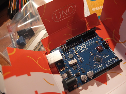
We got the Sparkfun ‘Starter Kit for Arduino’ from Proto-PIC. It arrived in less than 2 days and cost £42 including post and packing. This contains an Arduino Uno board, a breadboard, some LEDs, resistors, jumper leads, buzzer, potentiometers and more – but no instructions! I know a bit of programming, but hardly anything about electronics, so we had to dive in the deep end.
First we downloaded the Arduino software environment – you can get this for Windows, Linux and Macs. You use this to program the Arduino and tell it what to do. We plugged our new baby in to the computer by its USB lead, and uploaded the first sample bit of code included with the software – to make the onboard yellow LED (on pin 13) blink (keeping an eye out for weeping angels, of course).
Bread and butter
Next we decided to wire something up to the Arduino – we started with an external red LED which we would make light up. This required using the breadboard. Now I’ve seen breadboards before – funny plastic strips full of holes for making electronic prototypes – but I’d never used one. I had a vague idea the holes must be connected somehow underneath, but I didn’t know how. Thanks to a nameless professor, I now do:
So now I knew that the rows of holes on each side of the breadboard were wired together, allowing you to connect wires and LEDs and resistors and things without a soldering iron. I hate soldering irons, even if I am quite partial to the smell of flux. It’s a Proustian thing. I digress…
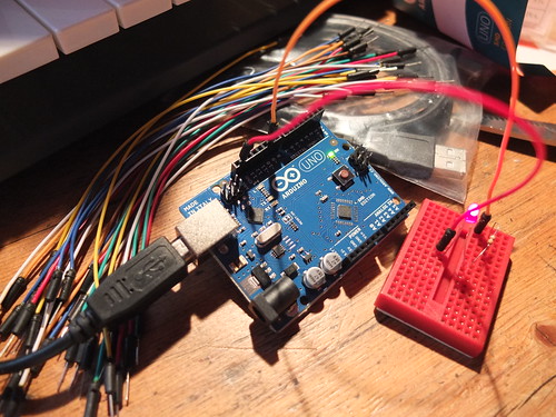
So, we took a jumper wire from pin 9 on the Arduino, and plugged it into the breadboard. It seems a resistor is needed to stop too much electricity getting to the LED, so we plugged one end of a 330 ohm resistor into the same row on the breadboard, and hopped the other end of it onto a new row. On that new row, we plugged in one leg of the red LED. William noticed that LEDs are not symmetrical – one leg is longer or bows out. This is because LEDs only work when they are the right way round – they only let electricity flow through in one direction.
We then took another jumper lead from the other leg of the LED and connected it back to the GND (earth) pin on the Arduino – this completes the circuit.
Rather than just blink on and off, we decided to make this LED pulse on and off gradually, using this sample ‘Fade’ code provided with the software. It worked first time! (If you want to study the code, you need to look at this page on a computer – it gets truncated on a phone screen.)
/*
 Fade

 This example shows how to fade an LED on pin 9
 using the analogWrite() function.

 This example code is in the public domain.

 */
int brightness = 0;    // how bright the LED is
int fadeAmount = 5;    // how many points to fade the LED by

void setup()  {
  // declare pin 9 to be an output:
  pinMode(9, OUTPUT);
}

void loop()  {
  // set the brightness of pin 9:
  analogWrite(9, brightness);

  // change the brightness for next time through the loop:
  brightness = brightness + fadeAmount;

  // reverse the direction of the fading at the ends of the fade:
  if (brightness == 0 || brightness == 255) {
    fadeAmount = -fadeAmount ;
  }
  // wait for 30 milliseconds to see the dimming effect
  delay(30);
}
The obvious thing to do now was to muck around with the code to alter its behaviour. We changed the fadeAmount variable to have different values, and discovered this made it pulsate at different rates. We also found that if the fadeAmount variable wasn’t a factor of 255, it didn’t pulsate very nicely. We looked at the code to figure out why that might be. The key is in the lines:
  // reverse the direction of the fading at the ends of the fade:
  if (brightness == 0 || brightness == 255) {
    fadeAmount = -fadeAmount ;
  }
So I did a bit of reading up on the syntax of the programming language to work out what that line of code actually means in plain English: ‘if the brightness is equal to zero, OR equal to 255, then flip the direction of the fade’. The two vertical pipe lines || mean ‘or’. As our fadeAmount might not be a factor of 255, the brightness might never exactly equal 255, so we changed it to flip the direction of fade when the brightness is greater than 240:
  // reverse the direction of the fading at the ends of the fade:
  if (brightness == 0 || brightness > 240) {
    fadeAmount = -fadeAmount ;
  }
So in about an hour, William (aged 9) and I had learnt a bit about programming, a bit of maths and a little bit of electronics.
Setting the Arduino free
That’s all well and good, but the Arduino was still connected to the computer by its umbilical USB cord. It felt like the computer was still in charge, even though we were just using it to supply electricity and occasionally reprogram the board. I wanted to cut the apron strings and set the Arduino free.
The Arduino has a socket for a DC power supply, so I rummaged around in The Drawer of Many Orphaned Phones, Leads and Power Supplies and found one that fitted the bill. It’s important to ensure it doesn’t supply too many volts – between 7 and 12 is ideal, and the plug must have a positive inner pin. I found this article very helpful: http://arduino.cc/playground/Learning/WhatAdapter
We unplugged the Arduino from the computer’s USB cable, plugged the power supply in – and it worked! Quite emotional, really – our first Arduino machine making its way in the world, all on its own. *Sniff*.
Next time: how we made red and yellow LEDs pulsate alternately.
—
I’ve subsequently found this tutorial, but we had fun working this out for ourselves! http://www.sparkfun.com/tutorials/145