In a previous project I made a simulation of a very simple microprocessor using a BBC micro:bit.
It’s coded in MakeCode blocks and, although it only has 4 instructions in its very reduced instruction set, it behaves in many ways like the microprocessors as used in the very first home computers, pioneering machines like the Altair 8800, the MOS Technology / Commodore Kim-1 and the Science of Cambridge MK14:
- Instead of being programmed with a high-level language like MakeCode, Scratch, Python or BASIC, its instructions are given using binary codes.
- Each binary code represents an instruction, an instruction with a piece of data attached (in this case an address where it should fetch some data from), or just a piece of data.
- When the program is run, the CPU fetches each instruction in turn from memory.
- It then decodes the instruction – it decides what the instruction means.
- The CPU next executes the instruction – it carries it out.
- It keeps track of where it is in the program using a program step counter and adds 1 to the program counter every time it needs to get a new instruction.
- It keeps fetching, decoding and executing instructions in order from memory until it reaches a halt instruction.
In effect, all our very simple CPU can do is add two numbers together and display the answer in binary using LEDs. It’s little more than a calculator, and not a very good one as it can’t subtract, multiply or divide.
It’s restricted to only 4 instructions because of the way I designed each word:
I limited myself to a 5-bit binary word, rather than the 8 bits as more normally used in early computer systems, because I wanted to be able to show the contents of each memory location on a row of the micro:bit’s LED display, with a lit LED representing a 1 and an unlit LED representing a 0.
Because I decided to store the operand (data, in this case an address) in the last 3 bits of instructions, that only left the first two bits to encode the actual instruction – the opcode.
This is clearly a bad idea, but if I still want to keep a 5-bit word to fit the display, I can split the opcode from the operand, and that’s what version 2 of my micro:bit CPU project does.
New CPU – new instructions
Now in my new design when the CPU fetches and decodes an instruction that needs an operand (some data or an address where it can find the data), it interprets the next address in memory as data, not an instruction. It does this by reading its contents and increasing the program step counter by 2 instead of by 1.
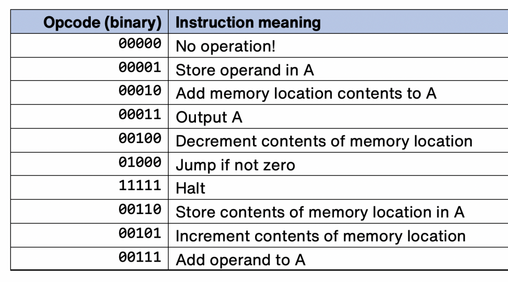
Now we have 5 whole bits to encode instructions, we can have not 4 but 31 instructions. Strictly speaking we could have 32, but I decided to treat myself and make 00000 a no operation opcode, an instruction that does nothing.
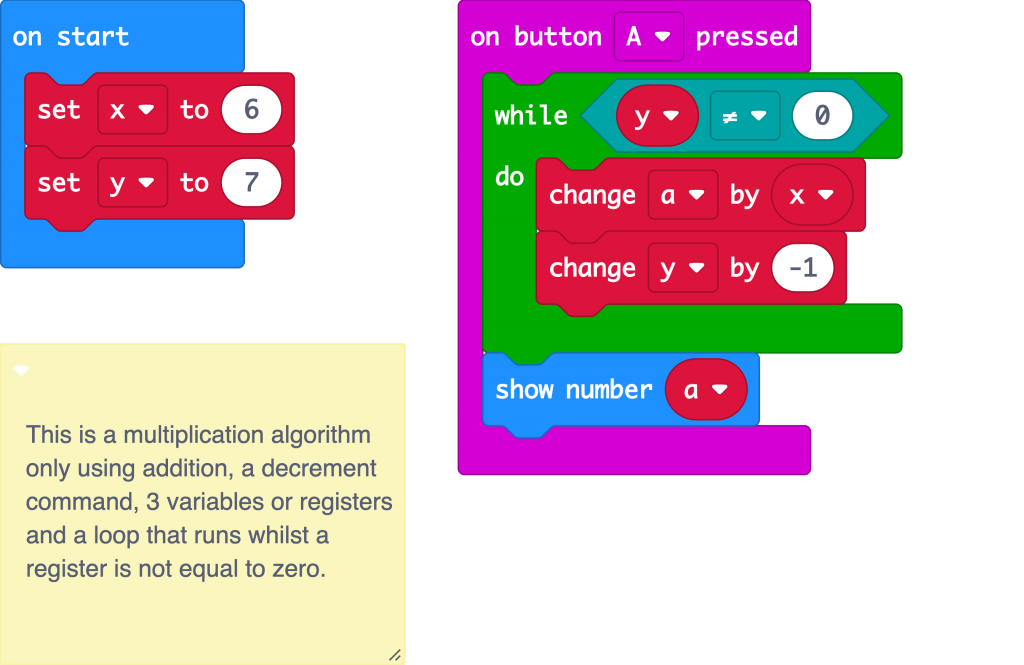
31 sounds like a lot, but even early 8-bit processors like the 6502 used in early home computers had over 100 instructions. To keep this project simple, but still do something more useful, I decided to use the minimum number of instructions I needed to implement a simple algorithm for multiplication:
This algorithm multiples 6 (held in variable x) by 7 (held in y) by adding 6 to variable a 7 times. It also deducts 1 from y each time, and when y reaches zero, the loop stops and it shows the answer on the LED display output,
To make this work in my micro:bit CPU, as well as the addition I can already do, I’m going to need the ability to reduce a variable by 1. Reducing something by 1 is called decrementing. Being able to increment and decrement numbers is useful when doing repetitive tasks, as we’ll see.
This very simple algorithm, however, requires two more things missing from our original micro:bit CPU:
- The ability to loop over sets of instructions.
- The ability to make a decision based on a condition – in this case, if y is zero, break out of the loop.
The second of these, the ability to change which code is executed depending on the result of a calculation, is fundamentally what makes a computer a computer, rather than just an adding machine. This ability to branch, to take different paths though sets of instructions, is also what separated Charles Babbage’s Analytical Engine from the simpler Difference Engine and made the Analytical Engine, although it was never built, theoretically a general-purpose computer.
For simplicity, I’ve decided to put the loop and the ability to jump out of a loop together in one instruction: JUMP IF NOT ZERO.
When any decrement instruction results in the number 0, a flag is set. Microprocessors have words of memory set aside to store several flags: these are single bits that record things like reaching zero (a zero flag), going into negative numbers (a negative flag) or numbers being too big to store in one word (a carry flag).
Our new CPU program uses a MakeCode variable zeroFlag as its zero flag. It’s a Boolean variable, which means like a microprocessor’s flag, it can only have two values, true or false, 1 or 0.
Here’s our new instruction set:

I could have added some registers or a stack to store data, and I may do that in a future version, but to keep things simple I only made one – A, or the accumulator. You can store numbers in it or add numbers to it. You can also increment or decrement contents of memory locations – so in effect you can use as many memory locations as variables or registers as you like.
As I develop this, I’ll probably add the ability to subtract numbers from the accumulator and the ability to store the accumulator in memory locations as well as store and add numbers directly.
We don’t use all of these instructions in our multiplication program, though, Here it is, a program to multiply 5 by 6 by adding 5 six times:
It adds the number 5 into our accumulator. It finds the number 5 by looking in the memory location specified in the next bit of memory: it tells the CPU to fetch the number from memory location 8.
Next it decreases the contents of location 9 by 1. This is so it can keep track of how many 5s we’ve added.
The instruction in memory location 4 tells it to jump back to location 0 if the zero flag has not been set. It keeps doing this until the zero flag is set when memory location 9 reaches zero.
Next it outputs the result, the number in the accumulator, as a binary number using the LEDs on the bottom row of the display. It then reaches the HALT instruction and stops decoding and executing any further instructions or data,
What’s the clock speed?
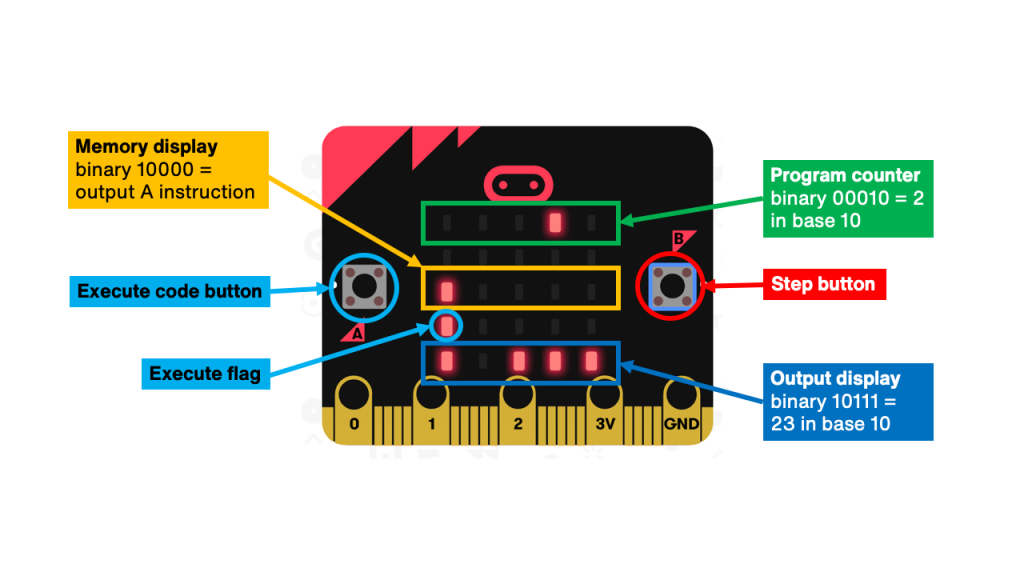
My micro:bit CPU doesn’t have a clock to keep fetching instructions, it relies on you to keep pressing button B to step through the program. Press button A to put the CPU in execute mode so that instead of just showing the contents of memory on the top row of LEDs, it will execute any instructions as well.
Try it out for yourself in the simulator below. Press button A to put it in program execute mode. You’ll hear a high tone as it starts. Keep pressing button B and you’ll see it loop around the same locations – it keeps adding 5 to the accumulator and reducing memory location 9 by 1 each time it does this. It adds 5 six times, and 5 lots of 6 is 5 x 6 or 30. When memory location 9 reaches 0, it shows the result of 5×6 in binary on the bottom row of the display and when it gets to the halt instruction it plays a low tone.
You can keep pressing button B but the program won’t execute – the program run LED has gone out and it won’t decode or execute any instructions any more.
Here’s the code that makes it work – quite a complex program, but I’ve tried to use functions where I can to make it easier to follow.
Open it in the MakeCode editor and see if you can create your own program for the improved micro:bit CPU!


