Use a micro:bit, some buttons, and wires to learn how a keyboard matrix works
Back in 2018 I had a go at making a simple pocket calculator using some micro:bits, and one thing that’s been bugging me ever since was the idea of connecting a numeric keypad to a micro:bit. Having not just 1 or 2 extra buttons, but 10, 12 or even 16 could make a micro:bit calculator much easier to use and much more like the real thing.
The BBC micro:bit only has 3 main GPIO (general purpose input-output) pins for connecting to the outside world, and that’s probably not going to be enough. If you use a breakout connector, however, you can access a whole load more.
There are some cunning projects that use resistors of different values to reduce the number of pins needed to read lots of button pushes. If you wire them together but with different resistors, you can measure an analogue input and work out which button was pressed.
Wiring it up
I took a different approach, though, deciding instead to use a pure matrix of keys. Although you can buy cheap matrix keypads, I happened to have a large bag of small push-buttons, so I decided to wire up my own matrix using a breadboard and some wire. Normal calculators and computer keyboards use matrices to reduce the amount of wiring needed to connect physical buttons to computational systems, and so in doing this I learnt a bit about how they work at a fundamental level.
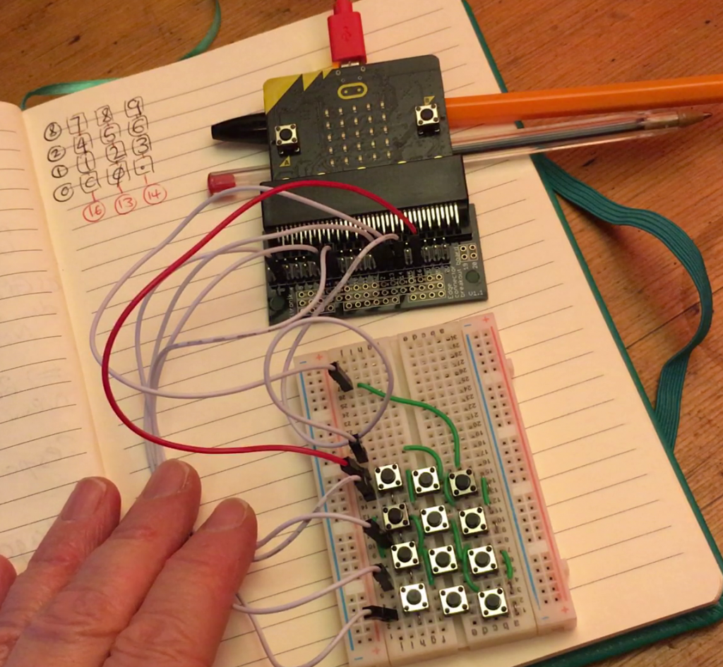
Wiring up the keypad was fun and quite therapeutic as a little break between Zoom calls. You can’t see in the picture but there are lots of tiny jumper wires underneath the buttons as well as the longer green wires. The buttons are staggered on the breadboard to make sure I only make electrical connections where I want.
The left leg of each button is wired together in a column. I then wired together the right leg of each button in rows. Now this looks like a lot of pins are needed, but imagine if you wired up each button separately, you’d need 12 pins for a 4×3 arrangement of buttons. Using a scanned matrix means you only need 7 pins, one for each row and column:
You can see circuit diagram of a 4×4 matrix here to get a better idea of the kind of wiring needed.
You have to be a bit careful which micro:bit pins you choose as some are used for other things like the display. I only need digital pins, however, as my keyboard scanner is going to send a digital signal output down each row in turn and then scan using a digital input every column in that row to see if any of the keys are pressed, completing the circuit and allowing the digital signal to pass.
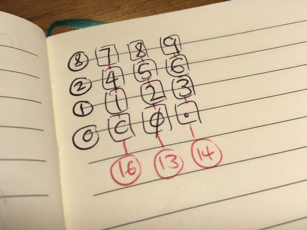
I picked pins 0, 1, 2 and 8 for my rows and 16, 13 and 14 for the columns. Pins 13 and 14 are also used for an SPI interface, but I’m not using SPI here so I can just use them as GPIO pins. I’m probably also going to need a 4×4 matrix to add operator keys eventually, but for that I’m going to need a bigger breadboard and this started out as a proof of concept which I didn’t really expect to work.
How the code works
For my proof of concept, I wrote a simple MakeCode program (code at the foot of this post) to send a digital write signal out on each row in turn, and then if a signal is incoming on any column, put the relevant number of symbol on the display.
I connected it up, flashed the program – and it worked!
A few caveats: it’s slow. You have to hold each button down for quite a long time before it registers. This is partly because a MakeCode ‘forever’ block introduces a small delay into your program. You can get round that by putting a ‘while true’ block around everything inside the forever block, but one added bonus of the small delay is that you can see the scanning happen in the simulator:
The program could also be improved by using functions to scan the columns and there’s a lot of work to do to transfer this into a working program that uses keypresses to do anything useful like a calculator, but this was an interesting activity to learn how to make and program a keypad from scratch and learn some fundamentals of how software and hardware combine at quite a low level.


