Having started to build a Ben Eater-style, 6502-based breadboard computer a few weeks ago, I’ve started to diverge my design a bit. Ben uses an Arduino Mega to monitor the status of the address and data bus, but I like old computers with blinkenlights and I also like the simplicity of a self-contained computer that doesn’t need an Arduino and another full-sized computer to display the data.
So I decided to keep the 16 LEDs I wired across the address bus, and added 8 new LEDs to the data bus, so I can monitor what’s going on, albeit in binary rather than in hexadecimal on an Arduino console screen.
Flashing an EEPROM
If we’re going to write a real program, instead of hard-wiring no operation instructions, we’ll need some sort of memory. The first kind we add is a read-only memory (ROM) so that the program remains when the power is off. This is used in old computers like the KIM-1 and Acorn System 1 to store the monitor program that allows you to enter code on a keypad and show things on an LED display. More complex systems like the Apple ][ and Commodore PET stored a BASIC interpreter in ROM as well as the machine's operating system.
As I want to keep changing the program as I develop the system, I need a kind of ROM that I can modify, which is where the EEPROM (electrically erasable programmable read-only memory) comes in.
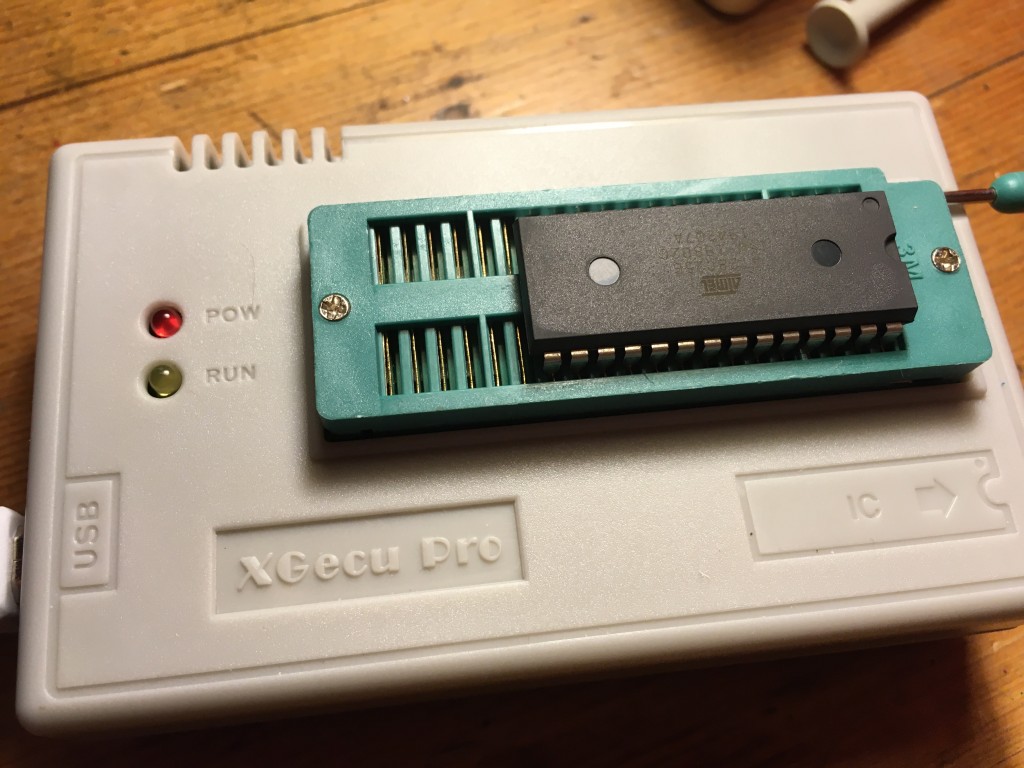
It was quite exciting flashing my first ever EEPROM. Back in the day (by which I mean the 1970s) I think EPROMs had to be erased using ultraviolet light and the process took a very long time, but now you can erase and flash a 32K EEPROM in a few seconds. I got an inexpensive programmer from China, which comes with Windows software but, being on a Mac, I installed a command line utility called minipro, which I installed using brew at the MacOS terminal command line:
brew install minipro
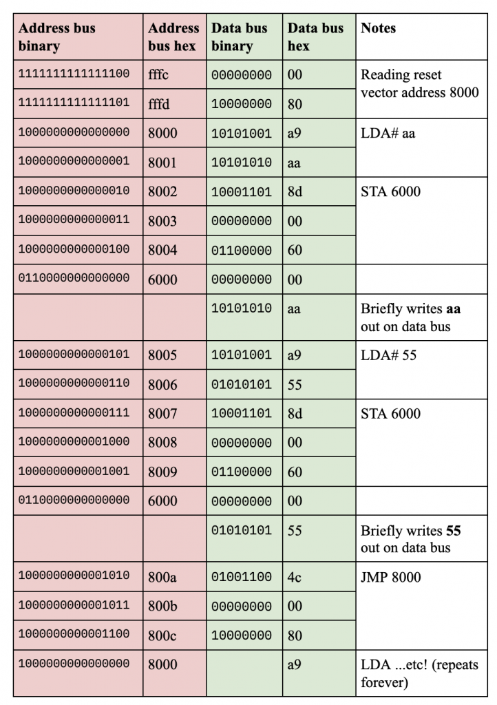
I modified Ben Eater's first program to add a loop and some different values. It just loads hex value aa (binary 10101010) into the accumulator, writes that out to memory location 6000, does the same with hex 55 (binary 01010101), and then loops back to the start of the program.
I also modified Ben's short Python program (code below) to create a binary file of exactly the correct length (32k) to fit on the EEPROM, which fills all the empty spaces with NOP (no operation) instructions - ea in hex.
You'll see that memory addresses are given 'backwards', i.e. address 6000 is coded as 00 then 60. This is the way that the 6502 (and some other processors) encode 2-byte addresses. It seems odd, but apparently there's a potential speed gain to be had from doing it this way. It's called little-endian encoding, after the pointless wars in Jonathan Swift's Gulliver's Travels over which end of a boiled egg you should crack open first. And, having done some machine code programming of my own, I finally understand it! The smaller (littler) byte of the two bytes comes first.
The other thing to note here is the 8000 address stored right near the end of the ROM, at locations 7ffc and 7ffd. This is the reset vector, which is super-important. When the 6502 processor is reset, it looks at these memory locations for the address at which it will find its instructions, the program you want it to run. In this build, we connect the EEPROM so that its first byte is at memory location 8000.
rom = bytearray([0xea] * 32768)
rom[0] = 0xa9   #LDA aa
rom[1] = 0xaa
rom[2] = 0x8d   #STA 6000
rom[3] = 0×00
rom[4] = 0×60
rom[5] = 0xa9   #LDA 55
rom[6] = 0×55
rom[7] = 0x8d   #STA 6000
rom[8] = 0×00
rom[9] = 0×60
rom[10] = 0x4c  #JMP 8000
rom[11] = 0×00
rom[12] = 0×80
rom[0x7ffc] = 0×00
rom[0x7ffd] = 0×80

with open(“rom.bin”, “wb”) as out_file:
  out_file.write(rom)
I connected the EEPROM programmer's USB cable to my laptop and burned the binary file created with the Python script on to it using this command:
minipro -p AT28C256 -w rom.bin
Wiring the ROM chip
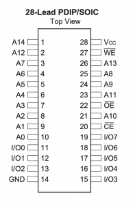
I used an Atmel AT28C256 32k EEPROM chip. This, I have to say, was an absolute pig to wire up - look how illogical the address bus pins are! Pin 7 is next to pin 12 which is next to pin 14.
I'm grateful to Pete Lomas for explaining to me that this illogical layout is caused by trying to maintain compatibility with older EPROMs and ROMs: no-one ever thought they'd be bigger than 1K, and room had to be found for the extra address lines.
So, I connected the EEPROM's address pins 0-14 to address bus pins 0-14 on the 6502 CPU, pin 14 to GND and pin 28 to +5v.
CPU address bus pin 15 goes via an inverter made from a NAND gate to the EEPROM’s CE (chip enable) pin 20. See Ben Eater's video for details. This is to ensure that the EEPROM is only enabled when the CPU is trying to address memory above location 8000.
Pin 27 WE (write enable) is tied high to +5v to prevent it being overwritten.
Pin 22 OE (output enable) is tied low (GND) as we want some output from the ROM.
The EEPROM I/O pins 0-7 are connected to data bus pin 0-7 on the CPU.
Running the program
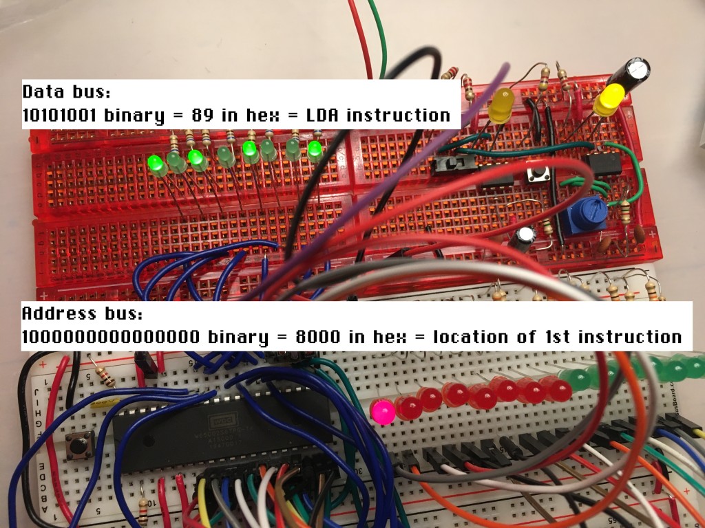
So, I powered it all up. As you'll see from the video at the top of the page, I wasn't sure if it was doing the right thing at first, but when I reset the CPU and single-stepped through the program, I discovered it was working perfectly. The picture above shows its status at address 8000, the first instruction of the program in my EEPROM. The data bus is showing binary 10101001, which is hex 89. 89 is the opcode for the 6502 LDA instruction, which is the first instruction!
I stepped through the whole program and confirmed every LED on the data bus is showing either the instruction opcode, or data being read or written.
The next steps will be to add the 6522 versatile interface adaptor (VIA) and a display. Ben Eater makes some LEDs blink next, but I feel I have enough blinkenlights, I may skip that and go straight to adding an LCD display driven from the VIA chip.
Eventually I'm going to want to add a keypad. I found a few articles about adding PS/2 keyboards, but I want something simpler and more KIM-1 like. I have some flexible 4x4 matrix keypads, which will do for entering hexadecimal numbers, but I'll need at least 4 more buttons I think to create a self-contained single-board computer: stop, go, up and down. If anyone has any advice about how to attach a small (say 4x5 or 5x5) keypad to a 6502, I'd love to hear it!


